WiringMini setup \ Troubleshooting
The WiringMini board was designed as an alternative for advanced Wiring users to include Wiring in small to mid range production of their projects and prototypes. It is as powerful as the Wiring I/O board but smaller in size, fitting in places where the wiring board might be too big for. The WiringMini can also be plugged directly into a breadboard for flexibility and it can be ordered with or without the pin headers soldered. The WiringMini board does not include a USB connector so the Wiring USBAdapter was designed as well. Many projects do not require the USB plug as a permanent component but just for programming the Wiring hardware, this reduces costs for production and deployment.
The WiringMini board includes a power regulator on it that converts input voltage into 5 volts VCC regulated voltage (to power itself and other components in your projects) making it very easy to power it from non-regulated power sources or batteries with no hassle or having to add extra power regulation circuits.
Step 1
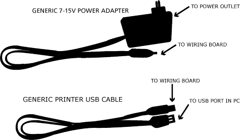
What's needed? The brand new WiringMini board, a Wiring USBAdapter chip, a generic USB printer cable to connect to the board to a computer and an external generic power adapter (optional).
Step 2
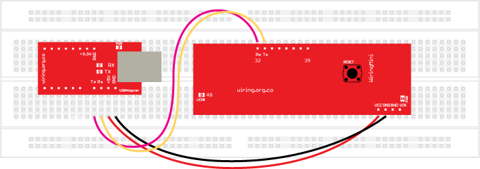
Power the WiringMini board accordingly. The WiringMini board can be powered from an external generic power adapter that provides voltage from 7-15 Volts, 500-1000mA, center positive; or it can be powered directly from the USB port of a computer by means of the USBAdapter board using 5V. Powering from the USB will fine for small experiments, but consider getting a power supply for connecting several devices to the board or high loads like servo motors. Below there are diagrams ilustrating diferent ways of powering the WiringMini board.
Powering from the Wiring USBAdapter (5 Volts): Note how the +5V from the USBAdapter goes directly into the VCC line of the WiringMini board. Ground (common) goes to Ground. Also note the Tx and Rx lines are connected to Serial serial port Rx and Tx lines of the WiringMini board respectively.
Note: Remember the port used to upload programs into the Wiring hardware is called Serial and it is available on pins 32 and 33. The second hardware serial port is available on pins 2 and 3 and it is called Serial1. Serial1 can be used to connect additional serial devices or even a second Wiring USBAdapter if needed.
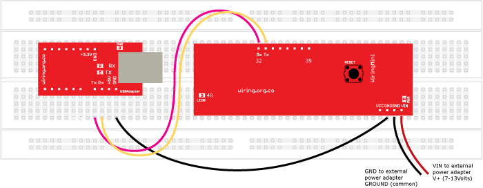
Powering from an external power supply (7-13 Volts): In this case the VIN line is connected to the positive V+ line of the external power adapter, this can be done because the WiringMini board has a power regulator included capable of converting higher voltages into regulated 5Volts (VCC). The external power supply ground line is connected to the WiringMini GND line. Note how the GROUND line from the USBAdapter also goes directly into the GND line of the WiringMini board. The Tx and Rx lines are connected to Serial serial port Rx and Tx lines of the WiringMini board respectively.
WARNING, NEVER CONNECT AN EXTERNAL POWER SUPPLY OR BATTERIES WITH VOLTAGES HIGHER THAN 5 Volts DIRECTLY TO VCC, use VIN instead. Doing this wrongly might damage your board permanently. If you are not sure about your connections or need additional support go to the discourse section and ask for help.
Step 3
Plug the Wiring USBAdapter board to the USB cable and then to the PC, the green power LED on the USBAdapter and WiringMini boards should come ON immediately. Now you are ready to go. By default a small program that blinks the amber LED on the WiringMini board is loaded, so you should be able to see the amber LED blinking a few seconds after powering your board. Now it is time to continue with the software setup process.
About the Wiring USBAdapter
The Wiring USBAdapter board can provide 5 or 3.3 volts VCC regulated power (to power a WiringMini or other components in your projects). The USB adapter is powered from the USB bus ONLY.
Here are some additional setups including the Wiring USBAdapter:
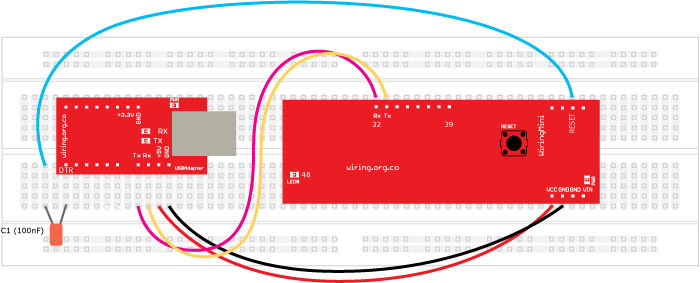
Enable automatic reset for code uploading: It is possible to enable the automatic reset feature in the WiringMini, so no need to press the reset button for uploading and restart a new program. Just add a 100nF capacitor between the DTR serial pin on the USBAdapter and the RESET pin on the WiringMini as shown in the diagram below:
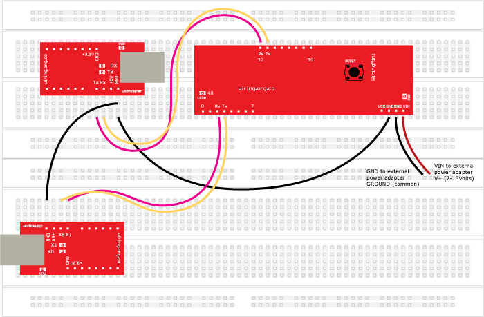
Using two USBAdapter boards with the WiringMini (one on each serial port): In this case one Wiring USBAdapter is used on Serial and the second in Serial1 serial ports. The WiringMini board is being powered from an external power source. The ground signal is shared by all the devices.
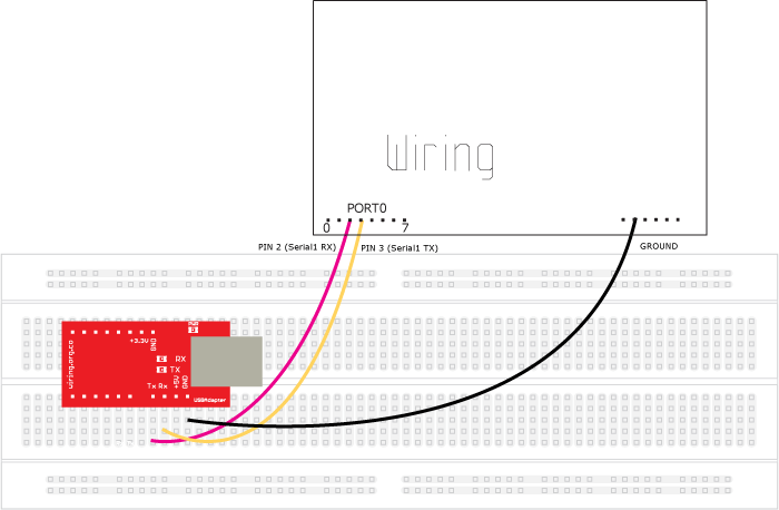
USBAdapter connected to the Wiring I/O board Serial1 serial port: In this case one Wiring USBAdapter is used on Serial1 with the Wiring /O board.
