
Burning a bootloader into a brand new DIP atmega168/328part to use it with Wiring
This tutorial introduces how to burn a bootloader from scratch of an atmega168/328 DIP package microcontroller on a breadboard to use it with Wiring.
Step 1
Setup the basic circuit to use the atmega168/328. The Wiring board shown in this tutorial will be used as programmer to burn the bootloader into the atmega168/328 DIP part. It is possible to use other board as the programmer all you have to do is to find the SS, SCK, MISO and MOSI pins on it to properly connect them to the atmega 168/328 DIP part.
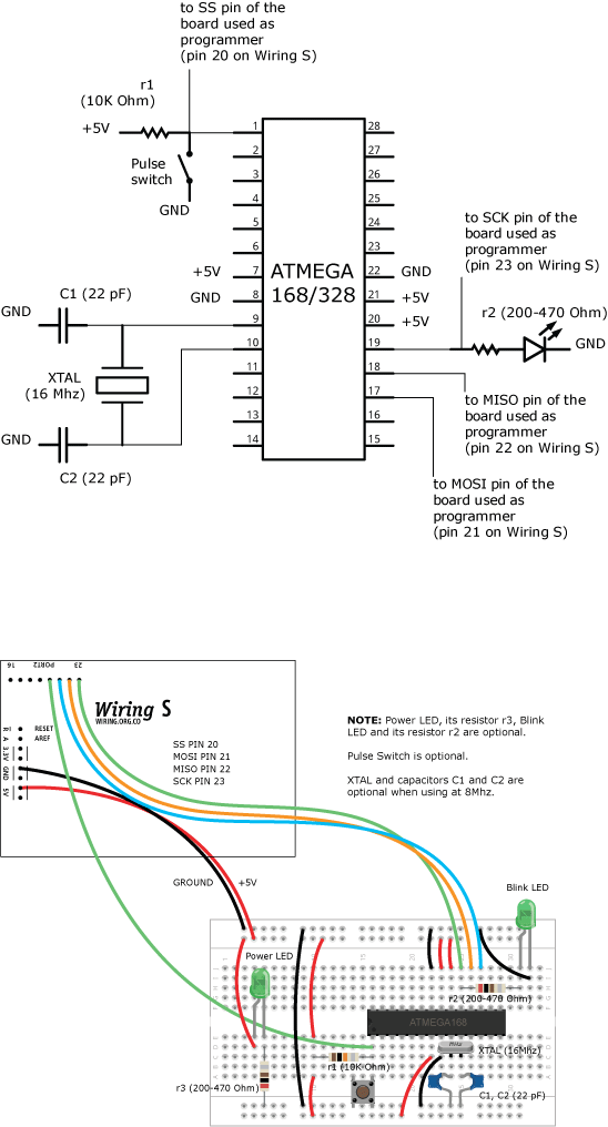
Note how the Power LED, and its resistor r3, the Blink LED and its resistor r2 are optional, they are useful for you to know of your circuit has power and later.
The Pulse switch is also optional, it will be used for manual reset of your DIP part.
The atmega168/328 can be used at 16Mhz requiring the XTAL and the two capacitors C1 and C2, we used (10 1KV) value for C1 and C2 and worked very well although the datasheet recommends to use 22pF for C1 and C2.
Step 2
Select the appropriate board you are going to use as programmer, for the purpose of this tutorial we used the Wiring S board, select the one you are planning to use on the menu Tools » Board » Wiring » Wiring S @ 16 MHz
Step 3
Select the appropriate Serial port for your board, for our setup the port selected in the menu was Tools » Serial Port » /dev/tty.usbserial-A400f7EN, find the right one for your programmer board.
Step 4
Load the WiringISP sketch located in the menu Help » Examples » Basics » WiringISP
Step 5
Upload the sketch into the programmer board pressing the Upload button on the main toolbar. Now your board will act as a programmer to burn the bootloader into a target microcontroller.
Step 6
Select the target microcontroller, for the purpose of this example we used an atmega168 part @ 16 MHz, in the menu Tools » Board » Atmel » ATmega168 @ 16MHz (crystal). If you are using a different DIP part select the one you have at the right speed.
Step 7
Select the menu Tools » Burn Bootloader » w/ Wiring ISP (use WiringISP sketch on another board) and this will start burning the new bootloader into your atmega168/328 DIP part.
After a few minutes a message telling burning bootloader was successful will be shown in the message box or an error message if the process failed. Errors might show if there are problems in the connections.
Next >> Using an FTDI USB to Serial breakout board to program your new chip using Wiring