
|


This example is for Wiring version 1.0 build 0100+. If you have a previous version, use the examples included with your software. If you see any errors or have comments, please let us know.
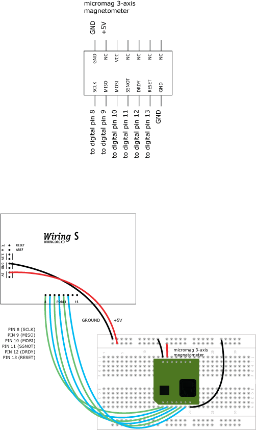
micromag 3-axis magnetic field sensor
Demonstrates the use of micromag 3-axis magnetic field sensor The sensor communicates using the ISP protocol. Based on Daniel Soltis example.
Demonstrates the use of micromag 3-axis magnetic field sensor The sensor communicates using the ISP protocol. Based on Daniel Soltis example.
int SCLKpin = 8;     // magnetometer pin 1
int MISOpin = 9;     // magnetometer pin 2
int MOSIpin = 10;    // magnetometer pin 3
int SSNOTpin = 11;   // magnetometer pin 4
int DRDYpin = 12;    // magnetometer pin 5
int RESETpin = 13;   // magnetometer pin 6
int x = 0;        // magnetic field x axis
int y = 0;        // magnetic field y axis
int z = 0;        // magnetic field z axis
int heading = 0;  // magnetic field heading

void setup()
{
  Serial.begin(9600);
  pinMode(WLED, OUTPUT);  // turn ON the board LED for diagnostics only
  digitalWrite(WLED, HIGH);
  pinMode(SSNOTpin, OUTPUT);
  pinMode(RESETpin, OUTPUT);
  pinMode(MOSIpin, OUTPUT);
  pinMode(SCLKpin, OUTPUT);
  pinMode(MISOpin, INPUT);
  pinMode(DRDYpin, INPUT);
  digitalWrite(SSNOTpin, LOW);
}

void loop()
{
  x = readAxis(0);  // read the x-axis magnetic field value
  y = readAxis(1);  // read the y-axis magnetic field value
  z = readAxis(2);  // read the z-axis magnetic field value
  heading = getHeading(x, y, z);  // calculates the magnetic field heading
  Serial.print("x: ");
  Serial.print(x, DEC);
  Serial.print("y: ");
  Serial.print(y, DEC);
  Serial.print("z: ");
  Serial.print(z, DEC);
  Serial.print("heading: ");
  Serial.print(heading, DEC);
  delay(20000);  // next reading in 20 seconds
}


// specific commands for the sensor

void sendBit(int bit)
{
  // send the bit on the RISING edge of the clock
  digitalWrite(MOSIpin, bit);
  delay(2);
  digitalWrite(SCLKpin, HIGH);
  delay(2);
  digitalWrite(SCLKpin, LOW);
  delay(2);
}

int receiveBit()
{
  // receive the data on the FALLING edge of the clock
  digitalWrite(SCLKpin, HIGH);
  delay(2);
  int bit = digitalRead(MISOpin);
  delay(2);
  digitalWrite(SCLKpin, LOW);
  delay(2);
  return bit;
}

float readAxis(int axis)
{
  // send eight bits, wait until the data is ready then receive 16 bits

  // pulse the reset
  digitalWrite(RESETpin, LOW);
  delay(2);
  digitalWrite(RESETpin, HIGH);
  delay(2);
  digitalWrite(RESETpin, LOW);
  delay(2);

  // send the command byte
  // set the time to read the magnetic sensors (ASIC period) as /2048
  sendBit(LOW);
  sendBit(HIGH);
  sendBit(HIGH);
  sendBit(LOW);
  sendBit(LOW);
  sendBit(LOW);

  // the last two bits select the axis
  if (axis == 0)  // x axis
  {
    sendBit(LOW);
    sendBit(HIGH);
  }
  else if (axis == 1)  // y axis
  {
    sendBit(HIGH);
    sendBit(LOW);
  }
  else  // z axis
  {
    sendBit(HIGH);
    sendBit(HIGH);
  }

  // wait until the DRDY line is high
  while (digitalRead(DRDYpin) == LOW)
  {
  }

  long total = 0;

  // receive result
  // the leftmost bit mark the number as positive or negative
  long sign = receiveBit();

  // the remaining bits are converted to an integer
  for (int i = 14; i >= 0; i = i - 1)
  {
    long thisbit = receiveBit();
    thisbit = thisbit << i;
    total = total | thisbit;
  }

  if (sign == 1)
  {
    total = total - 32768;
  }

  // set and return the appropriate variable
  if (axis == 0)
  {
    x = total;
  }
  else if (axis == 1)
  {
    y = total;
  }
  else
  {
    z = total;
  }
  return total;
}

int getHeading(float x, float y, float z)
{
  float heading = 0;
  if ((x == 0) && (y < 0))
    heading = PI / 2.0;
  if ((x == 0) && (y > 0))
    heading = 3.0 * PI / 2.0;
  if (x < 0)
    heading = PI - atan(y / x);
  if ((x > 0) && (y < 0))
    heading = -atan(y / x);
  if ((x > 0) && (y > 0))
    heading = 2.0 * PI - atan(y / x);
  return  int(degrees(heading));
}