
From electronic diagrams to actual circuit connections
A circuit diagram makes use of standardized symbols that represent electrical components or devices. It is easier to draw these symbols than drawing the actual pictures of the components. The actual components might change appearance as the electronics industry revises them or renders them obsolete. The diagrams describe the way in which the components are connected together electrically. There are drawn lines that represent wires or conductors between the appropriate connection points on the symbols; no particular type of wire or physical distance between components is implied; two components might be separated by a few inches or centimeters or a meter or feet.
The following tutorial translates from a circuit diagram to actually connecting components on a breadboard. Note that the circuit diagrams are the universal way of representing circuits; books, on-line resources, and materials use them to communicate the circuit connections. They are very useful compared with pictorial diagrams of the connections. The circuit diagrams presented in the Wiring website will work with any other type of microcontroller.
Materials: breadboard, LED, 200-450 Ohm resistor, jumper cables and a Wiring board
The following electronic diagram shows how to connect an LED to a microcontroller:
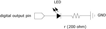
The next step would be to identify the components and their terminals:

Next, identify the connection nodes between components, connections between different components are formed by putting their legs (or terminales) in a common node:
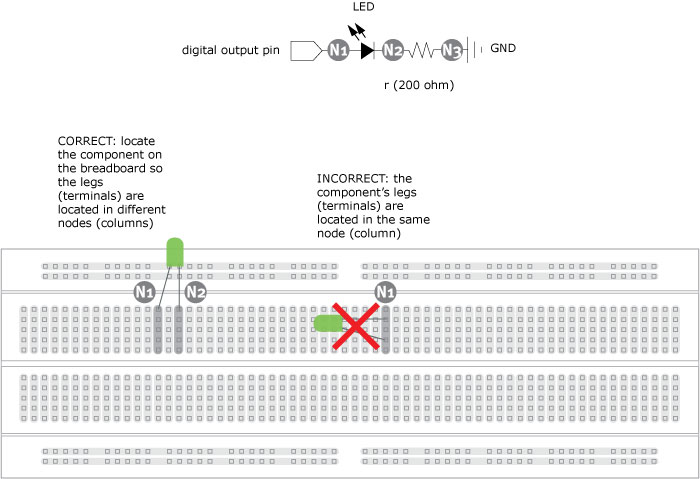
Note the difference between the correct and incorrect connections. In the correct version the two legs are on different columns (nodes), in the incorrect version the two legs are connected to the same column (node) which is equivalent to solder or tie together the two legs of the LED.
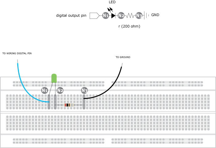
The LED has two legs, from the second diagram the leg maked as A is connected to a digital I/O pin (Node N1), the leg marked C is connected to the leg marked 1 on the resistor (Node N2) and the leg marked 2 on the resistor is connected to GROUND (Node N3). The LED is a polarized device, which means it matters the way it is connected, the resistor is not polarized so pins can be inverted with no effect on the circuit's behavior. To learn more about an specific component try to find its datasheet. Seach on the Web using the component's reference number to become familiar with its functions, terminals and specs.