
Setting up from scratch a new atmega168/328 to use it with Wiring
This tutorial introduces the setup from scratch of an atmega168/328 DIP package microcontroller on a breadboard and an FTDI USB breakout board (Sparkfun) to use it with Wiring. It assumes the bootloader is already loaded into the DIP part. Check out this tutorial to burn a bootloader into a brand new DIP part.
Step 1
Setup the basic circuit to use the atmega168/328 and the FTDI USB Serial FT232R breakout board.
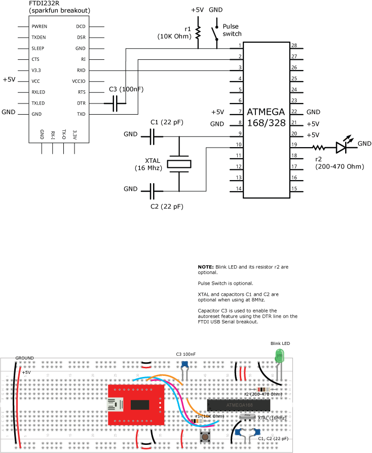
Note how the Blink LED and its resistor r2 are optional, they are useful for you to play later with the Blink example.
The Pulse switch is also optional, it is a manual reset for your microcontroller.
The atmega168/328 can be used at 16Mhz requiring the XTAL and the two capacitors C1 and C2, we used (10 1KV) value for C1 and C2 and worked very well although the datasheet recommends to use 22pF for C1 and C2.
Capacitor C3 is optional and it used to set the auto reset feature for your DIP part atmega168/328, otherwise you'll have to do a manual reset when uploading a new program and to restart when the new program is loaded.
Power is directly provided by the USB Serial breakout board VCC and GND lines to the rest of the circuit.
Step 2
Select the appropriate microcontroller you are going to use, for the purpose of this tutorial we used an atmega168 part @ 16 MHz, in the menu Tools » Board » Atmel » ATmega168 @ 16Mhz (crystal). If you are using a different DIP part select the one you have at the right speed.
Step 3
Select the appropriate Serial port for your USB Serial FTDI breakout, for our setup the port selected in the menu was Tools » Serial Port » /dev/tty.usbserial-A400f7EN, find the right one for your breakout board or cable.
Step 4
Load the Blink example sketch located in the menu Help » Examples » Basics » 1.Getting Started » Blink
Step 5
Upload the sketch into your new scratch "board" pressing the Upload button on the main toolbar. Happy Wiring!!