
Interfacing the Wiring hardware and MaxMSP
This tutorial introduces the basic interfacing between the Wiring hardware and MaxMSP http://cycling74.com. The brief for the tutorial will be to send data to the Wiring board, the Wiring board will read the data and turn ON or OFF the board LED accordingly. It assumes the Wiring software and MaxMSP are installed and the proper Wiring setup has been previously completed. For more Information on Wiring install check out the tutorials about Wiring installation and software setup.
Step 1
Copy and paste the following code on the Wiring editor: Verify your program is free of compiling errors by pressing the Compile/Verify button in the menu bar. Press the Upload button in the menu bar. In case of syntax errors the Wiring environment will print the error messages otherwise it will print the Upload was completed successfully, the uploading process triggers activity in the Rx/Tx LEDs on the Wiring hardware. The new program will start automatically after uploading. Use the Serial Monitor button to watch the data coming from the Wiring board, then close the Serial Monitor again. The full code for the example (both Wiring & MaxMSP is at the Examples -> Topics -> Other Software section here.
int val;          // variable to receive data from the serial port
int ledpin = 48;  // Wiring board LED

void setup()
{
  pinMode(ledpin, OUTPUT);  // pin 48 (on-board LED) as OUTPUT
  Serial.begin(9600);       // start serial communication at 9600bps
}

void loop() {
  if( Serial.available() )         // if data is available to read
  {
    val = Serial.read();           // read it and store it in 'val'
    if( val == 'H' )               // if 'H' was received
    {
      digitalWrite(ledpin, HIGH);  // turn ON the LED
    }
    else if( val == 'L' ) {
      digitalWrite(ledpin, LOW);   // otherwise turn it OFF
    }
  }
  delay(100);                      // wait 100ms for next reading
}
Step 2
Next step is to setup things in MaxMSP. Start MaxMSP.
Step 3
Double click the working area to add objects as shown:
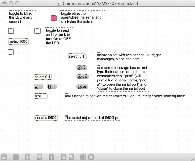
Step 4
Connect the objects as shown:
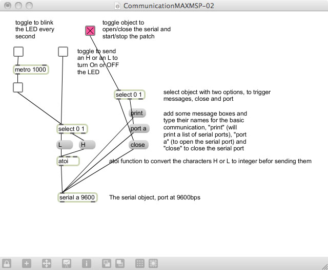
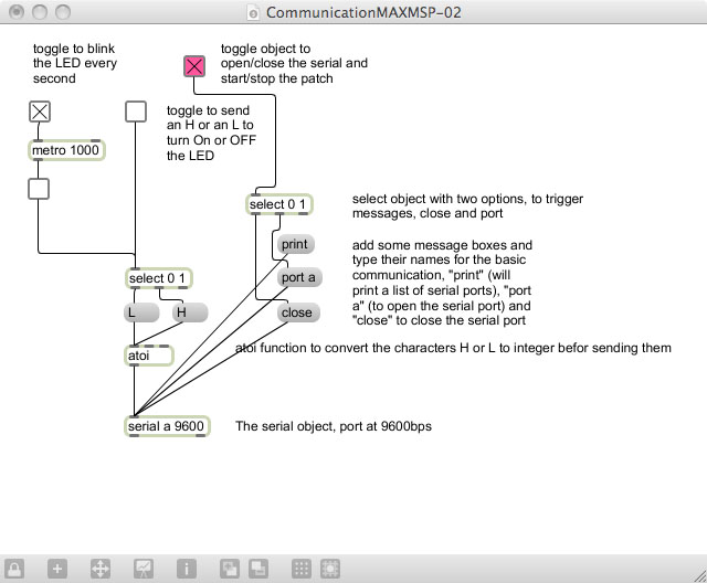
Step 5
Routing the connections sometimes produce a more readable patch, now the patch is ready to be tested, click the lock in the status bar and then click the toggle on the patch to start sending data. There are three toggles, one to open/close the serial port (color fucsia), one to send 'H' or 'L' to the board and one that sends 'H' or 'L' every second making the Wiring board LED to blink.
Next >> Reading in MaxMSP all the analog inputs from the Wiring board